Case Study: Legacy Transmission Pipeline Replacement Accomplished Despite Multiple Environmental and Logistical Hurdles
Background and Challenges
Replacing a legacy natural gas pipeline for integrity purposes can be routine—until it isn’t.
That was the case for a 24-inch pipeline—with a section of parallel 20-inch pipes—that serves a major metropolitan area.
Several challenges made this project unique:
-
-
Securing a Section 408 permit for the U.S. Army Corps of Engineers (USACE)
-
Crossing the pipeline over a levee
-
Boring under a river
-
Navigating a pump station
-
Designing multiple confined regulator station layouts
-
Planning detailed construction phasing to prevent service interruptions
-
Working with multiple municipalities
-

Installation occurs of a 24-inch steel gas transmission pipeline and associated 24-inch pig trap with full-port, automated ball valves.
Approach
The original design plan for the proposed 24-inch pipeline—an X65 steel pipe with 0.500-inch wall thickness and a maximum allowable operating pressure (MAOP) of 500 psig—was not to stay within a floodway. It was to bore underneath a USACE levee, which protects the metropolitan area from flooding, and place a new line where the existing line was located within the slope of the sump side of the levee. However, USACE wouldn’t allow any lines to cross under the levee, so a new strategy called for staying inside the floodway.
Construction included boring under a river. However, critical infrastructure could not be placed within the floodway. Halff’s team designed a method for running a significant portion of the pipeline inside the floodway, but then crossing it over the top of the levee so critical gas regulator stations—which step down the gas pressure so it can be delivered safely to end users—could be installed. A major flooding event would not allow access to the regulator stations if they were constructed within the floodway. The design had to ensure shutoff valves were accessible.
The Section 408 permitting process to accomplish these design alternatives was a more than two-year endeavor.
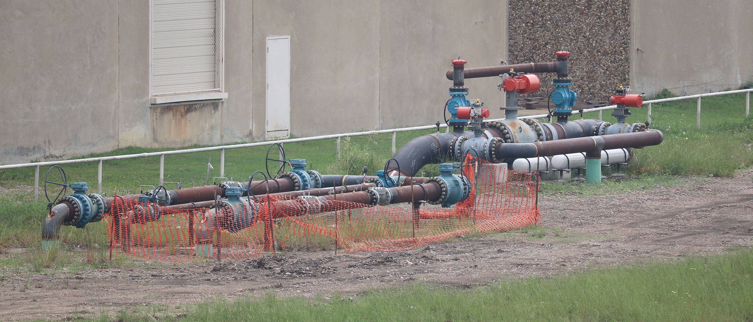
A mainline 24-inch full-port ball valve with bypass and straddle configuration feeds a regulator station.
Another hurdle for a mile-long section of the 24-inch replacement pipe was the need to bore through a significant city pump station sump, directly between two sets of columns supporting the pump discharge piping, which again provides protection from flooding. That called for coordinating with city officials to gain approval.
At the far eastern end of this project, where another 30-inch diameter line is connected, two pig traps were installed. Pipeline pigs are maintenance tools that inspect and clean lines and can determine the amount of corrosion that has developed inside the line. Two pig traps of different sizes were designed, one for each of the lines, along with interconnected piping. They feed a regulator station that was redesigned for a maximum throughput of 240 million standard cubic feet per day (MMSCFD).
-
Construction had to be phased to maintain gas flow to distribution lines while removing/replacing piping, valves, regulators and associated appurtenances.
-
Three trains with Mooney 12-inch dual-port Flowgrid regulators with noise controllers and a 16-inch bypass line were installed.
-
The design could not expand the existing facility, so three trains, a bypass and a 24-inch distribution line had to fit in a space less than 45-feet wide.
-
High-end luxury condominiums were constructed nearby, so regulator decibels had to be limited to less than 100 dB. This was also necessary to reduce vibration and enhance equipment life.
Bypasses were critical for this project. A multistep construction phasing plan was developed to ensure there were no service disruptions.

A new regulator station that serves the transmission pipeline includes three insulated trains utilizing 12-inch Mooney regulators and a 16-inch bypass.
Results and Benefits
This design effort, which included utilization of Halff’s Surveying, Subsurface Utility Engineering (SUE) and Environmental teams to resolve the easement boundary, provide topographic mapping, identify the existing utilities along the pipeline’s path and prepare the Section 408 permit, overcame several obstacles to ensure completion of the pipeline replacement without service interruptions.
Portions of the original easement for the replaced line were purchased in the early 1900s. The legacy pipeline, which had a MAOP of 364 psig, was upgraded to a functional MAOP of 500 psig. Small regulator stations that fed a nearby hospital district were redesigned to be safer and more efficient.
Five sections of pipeline were installed by horizontal directional drill (HDD). One bore under the river was approximately 1,500 feet long, and a second, which traveled to a 100-foot depth under the pump station sump, was approximately 5,000 feet long.
The most unique transmission pipeline project Halff has encountered accomplished its objective while also meeting environmental and logistical challenges.
Halff and its wholly-owned subsidiary, Halff TriTex, offer an extensive array of services to the energy industry including planning, permitting, engineering design, operating practices, regulatory/compliance requirements, environmental solutions and more. Learn more by writing to Info-OilandGas@Halff.com.
Recent Stories
Inside Halff: A Look at May 2026
Halff projects earned national recognition for engineering excellence, while the firm was honored for its impact on communities and the…

AML’s Convention | June 17-19, 2026
Come see Halff at AML’s 92nd Convention. Taking place June 17-19, 2026, in Little Rock, Arkansas. Event: Arkansas Municipal League,…